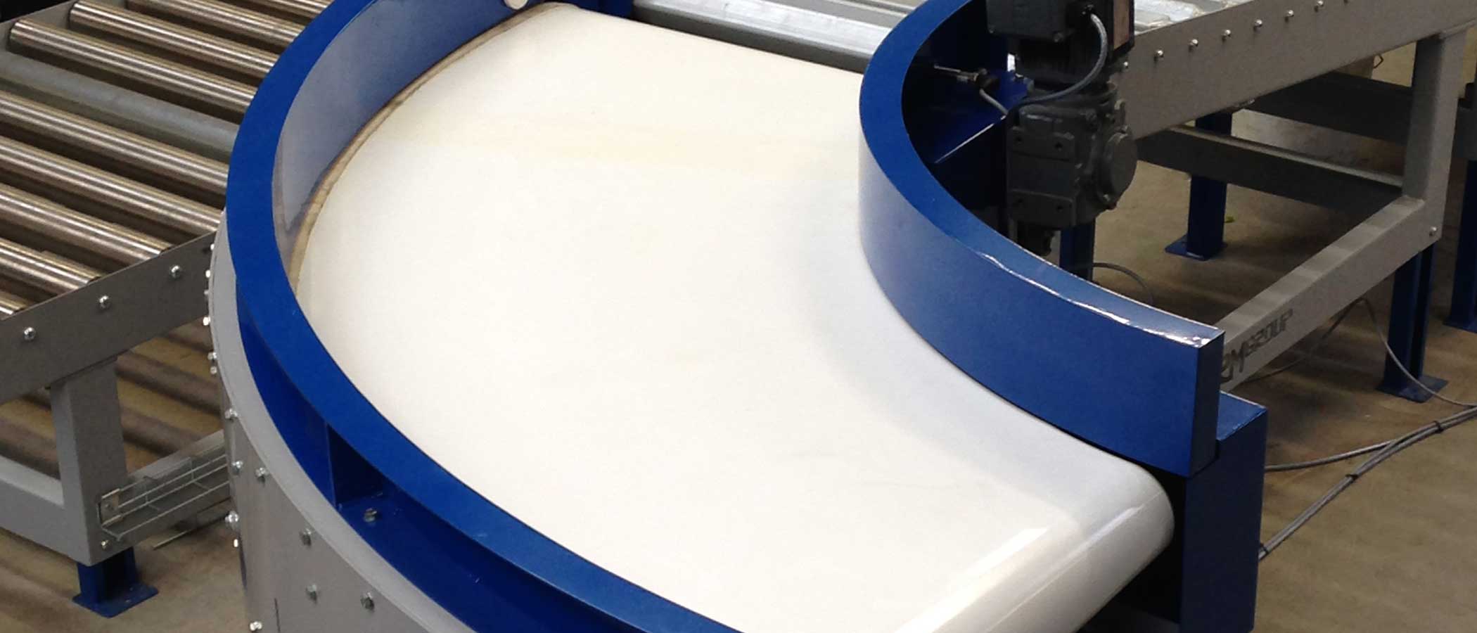
Gramac Quartz Belt Curve Technical Data and Specifications
Explore the technical specifications for Gramac Quartz powered belt curve conveyors, including operating capacities, conveyor speeds, frame dimensions, reliability data, maintenance information and standard model sizes. This guide covers the TR100, TS-TR100, TS-TR150, TR150, TR150 spiral and TR200 belt curve ranges, with AutoCAD drawings available for selected configurations.
Technical data is provided to assist with conveyor selection, system integration and layout planning. C/L refers to the conveyor centre line, while GMU refers to the geared motor unit. On mobile devices, swipe horizontally across the wide tables to view all specifications.
Belt Curve Operating Specifications
Compare the operating characteristics of Gramac Quartz belt curve models, including load capacity, ambient temperature, maximum belt speed, running noise and pulley specifications.
| Belt Curve Model | Max Load Capacity (kg/m*) | Ambient Operating Temperature (°C) | Max Speed Measured on C/L (m/s*) | Running Noise at 1 m (dBA) | Max Pulley Diameter (mm) | Minimum Pulley Bearing L10 Life |
|---|---|---|---|---|---|---|
| TS-TR150 AIRPORT BELT CURVE | 100 | -15 to +55 | 2.5 | 65 or less | 150 | 50000 |
| TS-TR100 BELT CURVES FOR INTRALOGISTICS | 60 | -15 to +55 | 2.0 | 65 or less | 100 | 50000 |
| TS-TR100 BELT CURVES FOR INDUSTRY | 50 | -15 to +55 | 2.0 | 65 or less | 100 | 50000 |
| TR200 HEAVY DUTY BELT CURVE | 200 | -15 to +55 | 1.5 | 65 or less | 200 | 50000 |
* Load capacities and speeds are measured along the centre line of the belt curve.
Belt Curve Frame Dimensions
The following dimensions provide key measurements for conveyor layout and installation, including overall frame depth, belt height relative to the underside of the frame, end overhang and outer-radius frame width. All dimensions are in millimetres.
| Belt Curve Model | Overall Frame Depth (mm) | Top of Belt to Underside of Frame (mm) | Maximum Overhang at End of Frame (mm) | Width of Frame at Outer Radius (mm) |
|---|---|---|---|---|
| TS-TR150 AIRPORT BELT CURVE | 320 | 270 | 25 | 80 |
| TS-TR100 BELT CURVES FOR INTRALOGISTICS | 260 | 215 | 20 | 70 |
| TS-TR100 BELT CURVES FOR INDUSTRY | 260 | 215 | 20 | 70 |
| TR200 HEAVY DUTY BELT CURVE | 370 | 315 | 25 | 80 |
| GRAMAC TS-TR150 BELT CURVES | |||||||||||||||
|---|---|---|---|---|---|---|---|---|---|---|---|---|---|---|---|
| Failure Modes, Mean Time Before Faiure (MTBF) Data (Assumes ambient conditions) | |||||||||||||||
| Angle | 30° | 45° | 60° | 90° | 180° | ||||||||||
| Speed at C/L | 0.5 M/s | 1.0 M/s | 1.5 M/s | 0.5 M/s | 1.0 M/s | 1.5 M/s | 0.5 M/s | 1.0 M/s | 1.5 M/s | 0.5 M/s | 1.0 M/s | 1.5 M/s | 0.5 M/s | 1.0 M/s | 1.5 M/s |
| Belt Assembly C/W Guide Rollers | 40000 hrs | 35000 hrs | 30000 hrs | 40000 hrs | 35000 hrs | 30000 hrs | 40000 hrs | 35000 hrs | 30000 hrs | 40000 hrs | 35000 hrs | 30000 hrs | 40000 hrs | 35000 hrs | 30000 hrs |
| Lagged Conical Drive Pulley | 40000 hrs | 40000 hrs | 35000 hrs | 40000 hrs | 40000 hrs | 35000 hrs | 40000 hrs | 40000 hrs | 35000 hrs | 40000 hrs | 35000 hrs | 35000 hrs | 35000 hrs | 30000 hrs | 30000 hrs |
| Conical Tall Pulley | 50000 hrs | 50000 hrs | 40000 hrs | 50000 hrs | 40000 hrs | 50000 hrs | 50000 hrs | 50000 hrs | 40000 hrs | 50000 hrs | 50000 hrs | 40000 hrs | 50000 hrs | 50000 hrs | 40000 hrs |
| Pulley Mounting Bearings | 50000 hrs | 50000 hrs | 40000 hrs | 50000 hrs | 40000 hrs | 50000 hrs | 50000 hrs | 50000 hrs | 40000 hrs | 50000 hrs | 50000 hrs | 40000 hrs | 50000 hrs | 50000 hrs | 40000 hrs |
| TSTR150 Belt Curves - Mean Time to Repair (MTTR) Data | ||||||||||
|---|---|---|---|---|---|---|---|---|---|---|
| Angle | 30° | 45° | 60° | 90° | 180° | |||||
| Location of Geared Motor | Inner Radius | Outer Radius | Inner Radius | Outer Radius | Inner Radius | Outer Radius | Inner Radius | Outer Radius | Inner Radius | Outer Radius |
| Belt Assembly C/W Guide Rollers | 17 mins | 15 mins | 17 mins | 15 mins | 19 mins | 17 mins | 20 mins | 18 mins | 24 mins | 22 mins |
| Lagged Conical Drive Pulley | 24 mins | 28 mins | 24 mins | 28 mins | 24 mins | 28 mins | 24 mins | 28 mins | 24 mins | 28 mins |
| Conical Tail Pulley | 21 mins | 25 mins | 21 mins | 25 mins | 21 mins | 25 mins | 21 mins | 25 mins | 21 mins | 25 mins |
| Pulley Mounting Bearings | 17 mins or 22 mins at GMU end | 17 mins or 22 mins at GMU end | 17 mins or 22 mins at GMU end | 17 mins or 22 mins at GMU end | 17 mins or 22 mins at GMU end | 17 mins or 22 mins at GMU end | 17 mins or 22 mins at GMU end | 17 mins or 22 mins at GMU end | 17 mins or 22 mins at GMU end | 17 mins or 22 mins at GMU end |
Weights
| TSTR150/2065/1030/A Airport Belt Curves - Weights of curves including Std SEW SA series GMU and 400mm high sidewalls, but excluding any support structures | ||||
|---|---|---|---|---|
| Angle of Curve | 30° | 45° | 60° | 90° |
| Weight (Kg) | 185 | 240 | 290 | 390 |
For non standard angles, take 85Kg off the above figures for the pulleys and GMU, pro rata the weight from the nearest angle to give a good approximation.
The TSTR150/2065/1030 Airport Belt Curve is approx. 12% lighter than it preceding model TR150/1985/1030/A because the lower bed / fixed integral under-guard has been eliminated in favour of a much lighter removeable under-guard.
Standard Sizes & Technical Data
Model Ref: TR100
- Max Loading = 50Kg/m measured along C/L
- Top of Belt to underside frame = 215mm
- Minimum pulley bearing L10 life = 50,000
- GMU: SEW SA47 (E2, IP54) helical worm gear as std
- Motor position: outside radius at discharge end as std
- Running Noise level: Dba @ 1m = 65 Dba or less
- Belt change time within 20 minutes
- Belts positively tracked by roller bearings fitted to outer edge
- Overall frame depth = 250mm
- Max overhang of end of frame to pulley = 25mm
- Tapered End Pulley Major Diameter = 100mm
- Std = 400V, 3ph, 50Hz supply (no controls included)
- Max Speed range (measured on C/L) = 2.0 M/s
- Ambient temperature range: -15°C to + 55°C
- High density Polypropylene Tapered End Pulleys
- Robust & rigid fabricated mild steel frame
| Outer Belt Rad (mm) | Effective Belt Width (mm) | Inner Belt Rad (mm) | Nominal C/L Rad (mm) | A) = Subtended Angles (degrees) | Model Designation | Link to Autocad | ||
|---|---|---|---|---|---|---|---|---|
| 45° | 90° | 180° | ||||||
| 700 | 300 | 400 | 550 | X | TR100/700/300/(A) |  | ||
| 700 | 400 | 300 | 500 | X | TR100/700/400/(A) | | ||
| 750 | 300 | 450 | 600 | X | TR100/750/300/(A) | | ||
| 800 | 400 | 400 | 600 | X | TR100/800/400/(A) | | ||
| 800 | 500 | 300 | 550 | X | TR100/800/500/(A) | | ||
| 1000 | 300 | 700 | 850 | X | TR100/1000/300/(A) | | ||
| 1000 | 400 | 600 | 800 | X | X | TR100/1000/400/(A) | | |
| 1000 | 500 | 500 | 750 | X | TR100/1000/500/(A) | | ||
| 1000 | 600 | 400 | 700 | X | TR100/1000/600/(A) | | ||
| 1100 | 500 | 600 | 850 | X | X | X | TR100/1100/500/(A) | |
| 1100 | 600 | 500 | 800 | X | X | TR100/1100/600/(A) | | |
| 1200 | 500 | 700 | 950 | X | X | TR100/1200/500/(A) | | |
| 1200 | 600 | 600 | 900 | X | X | X | TR100/1200/600/(A) | |
| 1300 | 500 | 800 | 1050 | X | X | TR100/1300/500/(A) | | |
| 1300 | 600 | 700 | 1000 | X | X | TR100/1300/600/(A) | | |
| 1300 | 700 | 600 | 950 | X | X | X | TR100/1300/700/(A) | |
| 1430 | 500 | 930 | 1180 | X | X | TR100/1430/500/(A) | | |
| 1430 | 600 | 830 | 1130 | X | X | TR100/1430/600/(A) | | |
| 1430 | 700 | 730 | 1080 | X | X | TR100/1430/700/(A) | | |
| 1430 | 800 | 630 | 1030 | X | X | X | TR100/1430/800/(A) | |
| 1500 | 500 | 1000 | 1250 | X | X | TR100/1500/500/(A) | | |
| 1500 | 600 | 900 | 1200 | X | X | TR100/1500/600/(A) | | |
| 1500 | 700 | 800 | 1150 | X | X | TR100/1500/700/(A) | | |
| 1500 | 800 | 700 | 1100 | X | X | TR100/1500/800/(A) | | |
| 1600 | 600 | 1000 | 1300 | X | X | TR100/1600/600/(A) | | |
| 1600 | 700 | 900 | 1250 | X | X | TR100/1600/700/(A) | | |
| 1600 | 800 | 800 | 1200 | X | X | X | TR100/1600/800/(A) | |
Model Ref: TS-TR100
- Max Loading = 75Kg/m measured along C/L
- Top of Belt to underside frame = 215mm
- Minimum pulley bearing L10 life = 50,000
- GMU: SEW SA47 (E2, IP54) helical worm gear as std
- Motor position: outside radius at discharge end as std
- Running Noise level: Dba @ 1m = 65 Dba or less
- Belt change time within 20 minutes
- Belts positively tracked by roller bearings fitted to outer edge
- Overall frame depth = 250mm
- Max overhang of end of frame to pulley = 25mm
- Tapered End Pulley Major Diameter = 100mm
- Std = 400V, 3ph, 50Hz supply (no controls included)
- Max Speed range (measured on C/L) = 2.5 M/s
- High density Polypropylene Tapered End Pulleys
- Robust & rigid fabricated mild steel frame
| Outer Belt Rad (mm) | Effective Belt Width (mm) | Inner Belt Rad (mm) | Nominal C/L Rad (mm) | A) = Subtended Angles (degrees) | Model Designation | Link to Autocad | ||||
|---|---|---|---|---|---|---|---|---|---|---|
| 30° | 45° | 60° | 90° | 180° | ||||||
| 1700 | 900 | 800 | 1250 | X | X | TS-TR100/1700/900/(A) | | |||
| 1800 | 900 | 900 | 1350 | X | X | TS-TR100/1800/900/(A) | | |||
| 1900 | 900 | 1000 | 1450 | X | X | X | X | X | TS-TR100/1900/900/(A) | |
| 2000 | 900 | 1100 | 1550 | X | X | X | X | X | TS-TR100/2000/900/(A) | |
Model Ref: TS-TR150
(Specifically designed for integration into low to medium capacity airport baggage handling systems).
- Max Loading = 90Kg/m measured along C/L
- Top of Belt to underside frame = 270mm
- Minimum pulley bearing L10 life = 50,000
- GMU: SEW SA47 (E2, IP54) helical worm gear as std
- Motor position: outside radius at discharge end as std
- Running Noise level: Dba @ 1m = 65 Dba or less
- Belt change time within 20 minutes
- Belts positively tracked by roller bearings fitted to outer edge
- Overall frame depth = 320mm
- Max overhang of end of frame to pulley = 25mm
- Tapered End Pulley Major Diameter = 150mm
- Std = 400V, 3ph, 50Hz supply (no controls included)
- Max Speed range (measured on C/L) = 2.5 M/s
- Ambient temperature range: -15°C to + 55°C
- High density Polypropylene Tapered End Pulleys
- Robust & rigid fabricated mild steel frame
| Outer Belt Rad (mm) | Effective Belt Width (mm) | Inner Belt Rad (mm) | Nominal C/L Rad (mm) | A) = Subtended Angles (degrees) | Model Designation | Link to Autocad | ||||
|---|---|---|---|---|---|---|---|---|---|---|
| 30° | 45° | 60° | 90° | 180° | ||||||
| 1985 | 1030 | 955 | 1470 | X | X | X | X | X | TS-TR150/1985/1030/(A) | |
| 2065 | 1030 | 1035 | 1550 | X | X | X | X | X | TS-TR150/2065/1030/(A) | |
| 2215 | 1030 | 1185 | 1700 | X | TS-TR150/2215/1030/(A) | | ||||
| 2100 | 1100 | 1000 | 1550 | X | X | X | X | TS-TR150/2100/1100/(A) | | |
Model Ref: TR150
- Quick release frame allows belt change in 12 mins
- Overall frame depth = 320mm
- Max overhang of end of frame to pulley = 25mm
- Tapered End Pulley Major Diameter = 150mm
- GMU: SEW SA47 (E2, IP54) helical worm gear as std
- Std = 400V, 3ph, 50Hz supply (no controls included)
- Running Noise level: Dba @ 1m = 65 Dba or less
- Belts positively tracked by roller bearings fitted to outer edge
- Max Loading = 110Kg/m measured along C/L
- Top of Belt to underside frame = 270mm
- Minimum pulley bearing L10 life = 50,000
- Max Speed range (measured on C/L) = 2.5 M/s
- PMM Drives can be fitted as an option
- Motor position: outside rad at discharge end as std
- Ambient temperature range: -15°C to + 55°C
- High density Polypropylene Tapered End Pulleys
| Outer Belt Rad (mm) | Effective Belt Width (mm) | Inner Belt Rad (mm) | Nominal C/L Rad (mm) | A) = Subtended Angles (degrees) | Model Designation | Link to Autocad | ||||
|---|---|---|---|---|---|---|---|---|---|---|
| 30° | 45° | 60° | 90° | 180° | ||||||
| 1600 | 800 | 800 | 1200 | X | X | X | X | X | TR150/1600/800/(A) | |
| 1715 | 1030 | 685 | 1200 | X | X | TR150/1715/1030/(A | | |||
| 1765 | 1030 | 735 | 1250 | X | X | TR150/1765/1030/(A)) | | |||
| 1815 | 1030 | 785 | 1300 | X | X | X | TR150/1815/1030/(A) | | ||
| 1885 | 1030 | 855 | 1370 | X | X | X | TR150/1885/1030/(A) | | ||
| 1915 | 1030 | 885 | 1400 | X | X | X | TR150/1915/1030/(A)* | | ||
| 1985 | 1030 | 955 | 1470 | X | X | X | X | X | TR150/1985/1030/(A)* | |
| 2015 | 1030 | 985 | 1500 | X | X | X | TR150/2015/1030/(A) | | ||
| 2065 | 1030 | 1035 | 1550 | X | X | X | X | X | TR150/2065/1030/(A)* | |
| 2115 | 1030 | 1085 | 1600 | X | X | X | TR150/2115/1030/(A) | | ||
| 2185 | 1230 | 955 | 1570 | X | X | X | X | X | TR150/2185/1230/(A)** | |
| 2215 | 1030 | 1185 | 1700 | X | TR150/2215/1030/(A)* | | ||||
| 2265 | 1230 | 1035 | 1650 | X | X | X | X | X | TR150/2265/1230/(A)** | |
| 2315 | 1030 | 1285 | 1800 | X | X | TR150/2315/1030/(A) | | |||
| 2515 | 1230 | 1285 | 1900 | X | X | TR150/2515/1230/(A) | | |||
| 2865 | 1030 | 1835 | 2350 | X | X | TR150/2865/1030/(A) | | |||
| 3495 | 1030 | 2465 | 2980 | 15° | 15° | 15° | 15° | 15° | TR150/3495/1030/(A)* | |
*Indicates models suitable for integration into airport baggage handling systems.
**Indicates models suitable for Out of Gauge airport baggage handling systems lines.
N.B. In addition to the above standard sizes TR150 Belt Curves can be manufactured to special order with an outside radius of up to 3500 mm and a max belt width of 1500mm. Please contact a GRAMAC QUARTZ representative to discuss your requirements.
Model Ref: TR150 Spirals
The following models can be manufactured as spiral belt curves with a change in elevation in 90° from 200mm rising in 50mm increments to a maximum of 500mm (pro rata for different angles).
- Quick release frame allows belt change in 15 mins
- Max overhang of end of frame to pulley = 25mm
- Tapered End Pulley Major Diameter = 150mm
- GMU: Braked SEW SA47 (E2, IP54) helical worm gear as std
- Std = 400V, 3ph, 50Hz supply (no controls included)
- Running Noise level: Dba @ 1m = 65 Dba or less
- Belts positively tracked by roller bearings fitted to outer edge
- Max Loading = 110Kg/m measured along C/L
- Minimum pulley bearing L10 life = 50,000
- Max Speed range (measured on C/L) = 2.5 M/s
- PMM Drives can be fitted as an option
- Motor position: outside rad at discharge end as std
- Ambient temperature range: -15°C to + 55°C
- High density Polypropylene Tapered End Pulleys
| Outer Belt Rad (mm) | Effective Belt Width (mm) | Inner Belt Rad (mm) | Nominal C/L Rad (mm) | A) = Subtended Angles (degrees) | Model Designation | Link to Autocad | ||||
|---|---|---|---|---|---|---|---|---|---|---|
| 30° | 45° | 60° | 90° | 180° | ||||||
| 1915 | 1030 | 885 | 1400 | X | X | X | TR150/1915/1030/(A)SP | | ||
| 1985 | 1030 | 955 | 1470 | X | X | X | X | TR150/1985/1030/(A)SP | | |
| 2065 | 1030 | 1035 | 1550 | X | X | X | X | TR150/2065/1030/(A)SP | | |
| 2185 | 1230 | 955 | 1570 | X | X | TR150/2185/1030/(A)SP | | |||
| 2215 | 1030 | 1185 | 1700 | X | TR150/2215/1030/(A)SP | | ||||
| 2215 | 1230 | 1035 | 1650 | X | X | TR150/2265/1230/(A)SP | | |||
| 2315 | 1030 | 1285 | 1800 | X | X | TR150/2315/1030/(A)SP | | |||
NB:
i) In addition to the angle and change of elevation the direction of rise or fall of a spiral bend must be specified.
ii) Spiral curves are supplied with a braked motor and high grip face belt as standard.
Model Ref: TR200
- Max Loading = 200Kg/m measured along C/L
- Top of Belt to underside frame = 315 mm
- Minimum pulley bearing L10 life = 50,000
- GMU: SEW SA47 (E2, IP54) helical worm gear as std
- Motor position: outside radius at discharge end as std
- Running Noise level: Dba @ 1m = 65 Dba or less
- Belt change time within 20 minutes
- Belts positively tracked by roller bearings fitted to outer edge
- Overall frame depth = 370 mm
- Max overhang of end of frame to pulley = 25mm
- Tapered End Pulley Major Diameter = 200mm
- Std = 400V, 3ph, 50Hz supply (no controls included)
- Max Speed range (measured on C/L) = 2.5 M/s
- Ambient temperature range: -15°C to + 55°C
- High density Polypropylene Tapered End Pulleys
- Robust & rigid fabricated mild steel frame
| Outer Belt Rad (mm) | Effective Belt Width (mm) | Inner Belt Rad (mm) | Nominal C/L Rad (mm) | A) = Subtended Angles (degrees) | Model Designation | ||
|---|---|---|---|---|---|---|---|
| 30° | 90° | 180° | |||||
| 1300 | 600 | 700 | 1000 | X | X | TR200/1300/600/(A) | |
| 1500 | 400 | 1100 | 1300 | X | X | TR200/1500/400/(A) | |
| 1500 | 600 | 900 | 1200 | X | X | TR200/1500/600/(A) | |
| 1800 | 600 | 1200 | 1500 | X | X | X | TR200/1800/600/(A) |
| 2100 | 600 | 1500 | 1800 | X | X | X | TR200/2100/600/(A) |
| 2100 | 800 | 1300 | 1700 | X | X | X | TR200/2100/800/(A) |
| 2500 | 600 | 1900 | 2200 | X | X | X | TR200/2500/600/(A) |
| 2500 | 800 | 1700 | 2100 | X | X | X | TR200/2500/800/(A) |
NB:
In addition to the above standard sizes TR200 Belt Curves can be manufactured to special order with an outside radius of up to 3000 mm and a max belt width of 1500mm. Please contact a GRAMAC QUARTZ representative to discuss your requirements.
Gramac Quartz Belt Curve Technical Specifications FAQs
A Gramac Quartz belt curve conveyor is a powered conveyor designed to transport products or baggage around a bend while maintaining a continuous conveying surface. The range includes belt curves for industrial conveying, intralogistics, airport baggage handling and heavy-duty applications.
The Gramac Quartz belt curve ranges covered in this technical guide include TR100, TS-TR100, TS-TR150, TR150, TR150 Spiral and TR200. Each range has different operating capacities, dimensions and standard configurations to suit particular conveyor system requirements.
Maximum load capacity depends on the belt curve model. The published specifications list 50 kg per metre for the TR100, 110 kg per metre for the TR150 and TR150 Spiral, and 200 kg per metre for the TR200 heavy-duty belt curve. Load capacities are measured along the conveyor centre line (C/L). Refer to the individual model specifications for the appropriate capacity.
Maximum operating speed varies by model. The published specifications list speeds of up to 2.5 metres per second for selected Gramac Quartz belt curves, measured along the conveyor centre line. The correct operating speed should be confirmed against the relevant model specifications and application requirements.
Yes. The TS-TR150 belt curve is specifically designed for integration into low- to medium-capacity airport baggage handling systems. Selected TR150 models are also identified as suitable for airport baggage handling, including out-of-gauge baggage handling system applications.
Yes. AutoCAD DWG drawings are available for selected Gramac Quartz belt curve configurations. Click the download icon in the relevant standard sizes table to access the drawing. Some models have more than one DWG download because separate drawings are provided for different curve angles.
Available curve angles depend on the model and dimensions. The standard sizes tables include configurations at 30°, 45°, 60°, 90° and 180°. Refer to the angle columns in the relevant model table to identify the listed configurations.
Yes. TR150 belt curves can be manufactured to special order with an outside radius of up to 3,500 mm and a maximum belt width of 1,500 mm. TR200 belt curves can also be manufactured to special order, with an outside radius of up to 3,000 mm and a maximum belt width of 1,500 mm. Contact Amber Industries to discuss non-standard conveyor requirements.
Yes. TR150 Spiral belt curves are available for applications requiring a change in elevation around a bend. The published specifications describe elevation changes from 200 mm to 500 mm over a 90° curve, in 50 mm increments. Spiral curves are supplied with a braked motor and high-grip belt as standard. The required angle, elevation change and direction of rise or fall must be specified.
This page provides belt curve operating specifications, maximum load capacities, conveyor speeds, frame dimensions, standard sizes, available angles, maintenance information, mean time between failure (MTBF) data, mean time to repair (MTTR) data and AutoCAD DWG downloads for selected configurations. The information can assist with conveyor selection, layout planning and system integration.