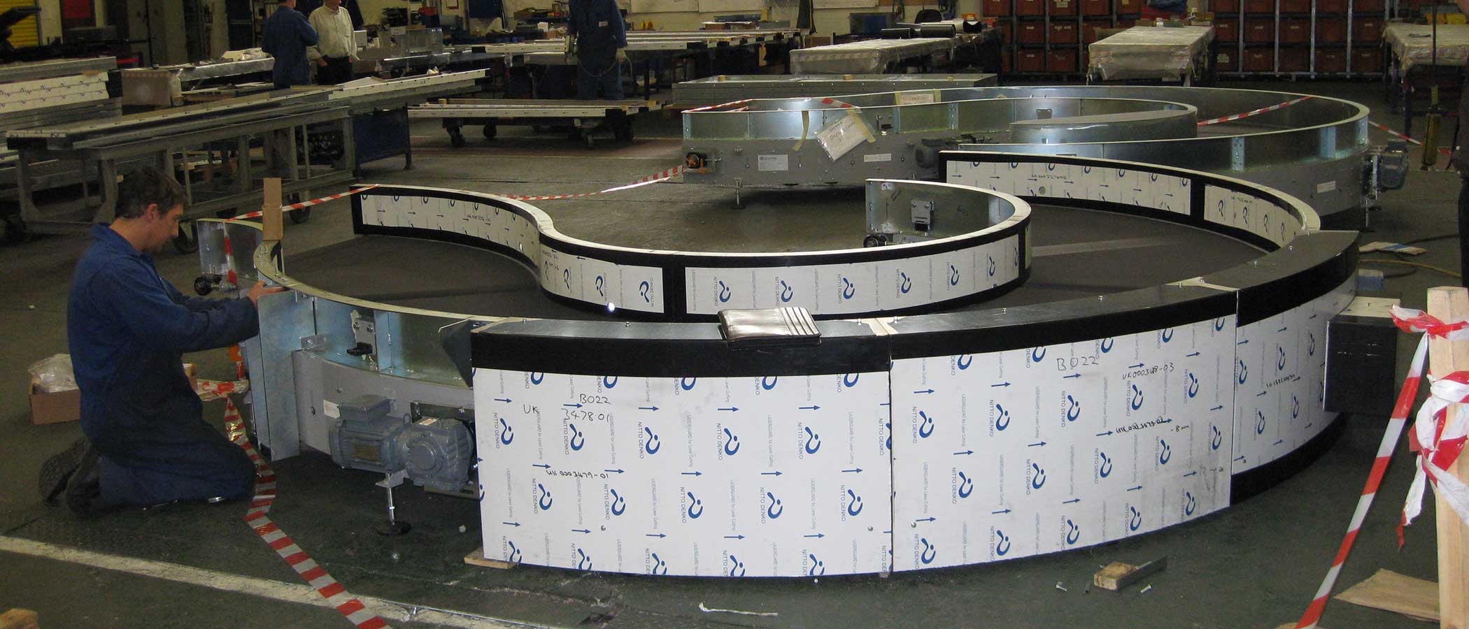
TS-TR150 Airport Belt Curves
Gramac Quartz’s TS-TR150 range of belt curves have been purposely designed for incorporation into the most demanding high speed airport baggage handling systems. When operating under normal conditions, i.e. an ambient environment, and they are properly maintained a lifespan well in excess of 15 years can be anticipated.
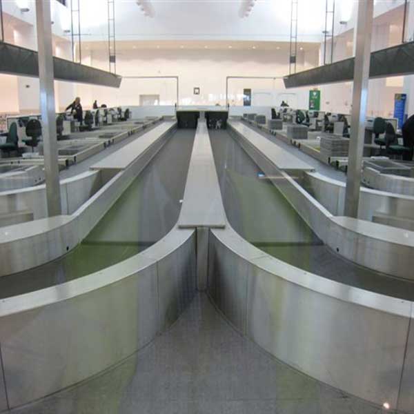
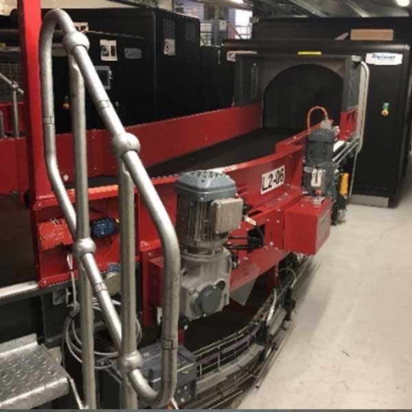
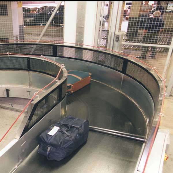
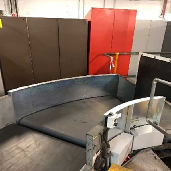
Standard Belt Curve Formats for Integration Into Airport Baggage Handling Systems
| Outer Belt Rad (mm) | Belt Width (mm) | Inner Belt Rad (mm) | Nominal C/L Rad (mm) | (A)=Subtended Angles | Model Designation | ||||
|---|---|---|---|---|---|---|---|---|---|
| 30° | 45° | 60° | 90° | 180° | |||||
| 1765 | 1030 | 735 | 1250 | X | X | X | X | X | TS-TR150/1765/1030/(A) |
| 1915 | 1030 | 885 | 1400 | X | X | X | X | X | TS-TR150/1915/1030/(A) |
| 1930 | 1030 | 900 | 1415 | X | X | X | X | X | TS-TR150/1930/1030/(A) |
| 1985 | 1030 | 955 | 1470 | X | X | X | X | X | TS-TR150/1985/1030/(A) |
| 2065 | 1030 | 1035 | 1550 | X | X | X | X | X | TS-TR150/2065/1030/(A) |
| 2185 | 1230 | 955 | 1570 | X | X | X | X | X | TS-TR150/2185/1230/(A) |
| 2265 | 1230 | 1035 | 1650 | X | X | X | X | X | TS-TR150/2265/1230/(A) |
| 2365 | 1230 | 1135 | 1750 | X | X | X | X | X | TS-TR150/2365/1230/(A) |
N.B. Any angle between 15° and 180° can be manufactured on request
The TS-TR150 airport belt curve can be manufactured in bespoke formats with a maximum outer radius of 3500mm and a maximum belt width of 1500mm.
Spiral Belt Curves
Spiral belt curves can also be manufactured with a change in elevation of up to 500mm in 90° (pro rata for different angles). Spiral belt curves are normally fitted with a high grip faced belt to prevent slippage of the baggage and a braked geared motor unit.
Spiral Belt Curve Formats for Integration Into Airport Baggage Handling Systems
| Outer Belt Rad (mm) | Belt Width (mm) | Inner Belt Rad (mm) | Nominal C/L Rad (mm) | (A)=Subtended Angles | Model Designation | ||||
|---|---|---|---|---|---|---|---|---|---|
| 30° | 45° | 60° | 90° | 180° | |||||
| 1765 | 1030 | 735 | 1250 | X | TS-TR150/1765/1030/(A) SP |
||||
| 1915 | 1030 | 885 | 1400 | X | TS-TR150/1915/1030/(A) SP |
||||
| 1930 | 1030 | 900 | 1415 | X | TS-TR150/1930/1030/(A) SP |
||||
| 1985 | 1030 | 955 | 1470 | X | X | X | X | TS-TR150/1985/1030/(A) SP |
|
| 2065 | 1030 | 1035 | 1550 | X | X | X | X | TS-TR150/2065/1030/(A) SP |
|
| 2185 | 1230 | 955 | 1570 | X | TS-TR150/2185/1230/(A) SP |
||||
| 2265 | 1230 | 1035 | 1650 | X | TS-TR150/2265/1230/(A) SP |
||||
| 2365 | 1230 | 1135 | 1750 | X | TS-TR150/2365/1230/(A) SP |
||||
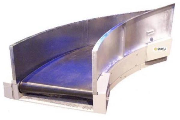
Configuration
Drive Units: Hollow shaft geared motor units are usually mounted at the discharge end, horizontally oriented on the outer radius or alternatively vertically mounted on the inner radius. SEW Eurodrive motors are standard – other manufacturers motors can be supplied and fitted.
Belts: Endless belts with min no. of vulcanised spliced finger joints are supplied in 2 ply polyester backed, black PVC top, low friction, low noise material, fire resistant to ISO 340. Spiral curves are fitted with ‘gripface’ of ‘rough top’ belts. Other types of belt are available by request.
Side Walls: Demountable fabricated sheet steel sidewalls can be fitted to height of 450mm above top of belt. Mounting brackets and holes for fitting PEC’s and reflectors can be incorporated.
Guarding: Removeable galvanised sheet steel panels provide underside guarding as standard. The belt guide rollers are fully guarded on the top, bottom and around the terminal ends.
Supports: Supports are ‘H’ type legs c/w anti-vibration footpads with +/-50mm adjustment or locking castors . Alternatively for close to floor level Curves ‘outriggers’ are fitted. Side brackets are fitted where curves are to be suspended from the ceiling.
Finish: The main body, sidewalls and supports are all powder coated in any standard RAL or BS colour of the customer’s choice. Alternatively a galvanised finish can be achieved for humid or exposed locations.
Maintenance: O&M manuals are provided with detailed explanations of the recommended periodic maintenance routines. Sealed for life bearings minimise lubrication requirements. Moving parts guards are lightweight for easy removal. The heaviest component is usually the geared motor at up to 35Kg. A maintenance viewing window is provided and no special tools are required. Belts can be changed in under 20 minutes.
For further detailed technical information refer to the ‘Belt Curve Technical Specifications’ webpage.
